UCD Formula Student · 2027
2027 chassis
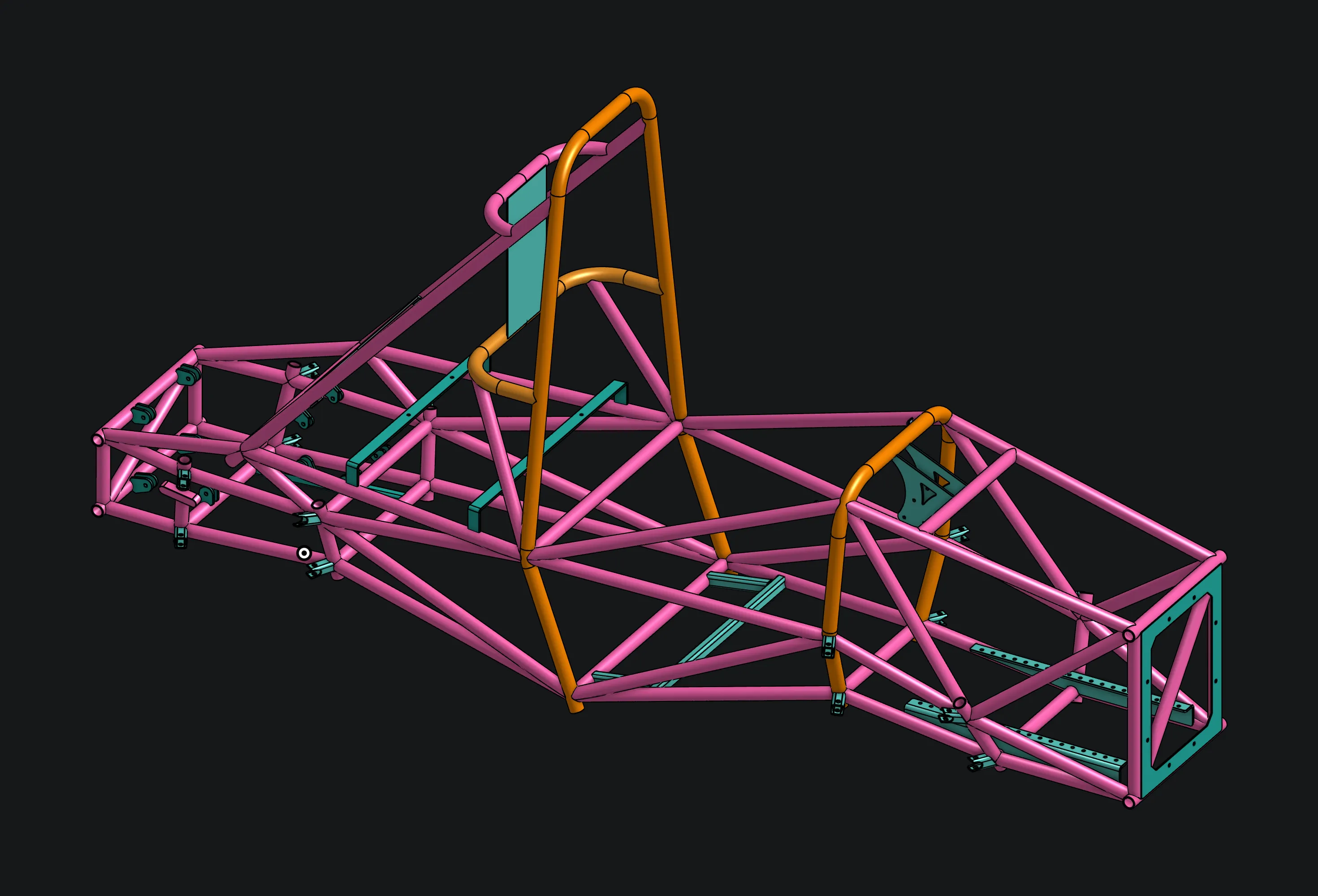
UCD Formula Student's first full chassis redesign. I built the method that set its stiffness target, and the design now beats it by 13% while weighing the same as last year's frame.
- Role
- Chassis mechanical engineer, stiffness targeting
- Team
- UCD Formula Student
- Tools
- Onshape, Ansys Mechanical (beam FEA)
- Progress
- In progressAnalysis · 3/5
- 01 Result
- +68%torsional stiffness at the same frame mass
- 02 Result
- 1,980 Nm/°against a 1,750 Nm/° target
- 03 Result
- ~54 kgestimated with all mounts, about 2 kg lighter than 2026
The brief
UCD Formula Student had always redesigned half of the chassis each year. For 2027 the team started from a clean sheet. The goals were a stiffer frame at no extra mass, plus mounts for a rocker-actuated suspension instead of the previous direct-acting layout.
Setting the target
Before designing anything, we needed to know how stiff was stiff enough. In a corner, load transfers to the outside tyres, and the team sets how that transfer is split between the front and rear axles by choosing the roll stiffness at each end. That split is a large part of the car’s handling balance. A chassis that twists between the axles quietly undoes it. An infinitely stiff chassis would be infinitely heavy, so the real question is how much of the intended roll split we’re willing to lose to flex.
This was my main contribution: I wrote the team’s method for setting the target, with a calculator the rest of the team can rerun. It’s based on Deakin, Crolla, Ramirez and Hanley’s paper The Effect of Chassis Stiffness on Race Car Handling Balance (SAE 2000-01-3554), with pointers from Design, Analysis and Testing of a Formula SAE Car Chassis.
The paper gives a rule of thumb: the acceptable loss X (in percent) divided by 20 equals the ratio of total roll stiffness to chassis stiffness. But that rule was read from a graph for a car with a 50:50 weight split and a 60:40 roll split, and ours is 55:45 and 52:48. So I derived a closed-form version from the paper’s own equations. It models the car as three springs in series: front roll stiffness ρK, the chassis Kch, and rear roll stiffness (1 − ρ)K. Solving for the torque the chassis carries gives the front load transfer distribution:
LTD_front = w + (ρ − w)·η
η         = 1 / (1 + r·ρ(1 − ρ))
r         = K / K_ch
Here η is the fraction of the intended roll split that survives the flex. A rigid chassis gives η = 1, so the split is exactly what the suspension was set up for. A very soft one gives η = 0, so the split collapses to the weight distribution w. Defining the loss as X = 1 − η and rearranging gives the target directly:
K_ch = K(1 − X)·ρ(1 − ρ) / XFor our car, that means a total roll stiffness of K = 542 Nm/°, with ρ = 0.52, w = 0.55 and an acceptable loss of 8%. The result is an effective stiffness at the wheels of 1,556 Nm/°, about 2.9 times the roll stiffness. That’s 10% stiffer than the paper’s rule of thumb asks for, which matters because the rule is only claimed for cars near a 50:50 weight split.
The chassis isn’t the only thing that flexes. Wishbones and uprights add compliance in series, so we gave them a placeholder target of 16,000 Nm/°, about ten times the effective target, to be replaced with FEA or measured values. For simulation, that converts to an equivalent spring of about 1,270 N/mm at each corner, assuming a 1.2 m track. Taking the installation flex out leaves a chassis-only target of 1,723 Nm/°, which we rounded to 1,750 Nm/°. An earlier version of the report used a higher roll stiffness of 713 Nm/°, which gave about 2,200 Nm/°. Lowering the roll stiffness brought the target down.
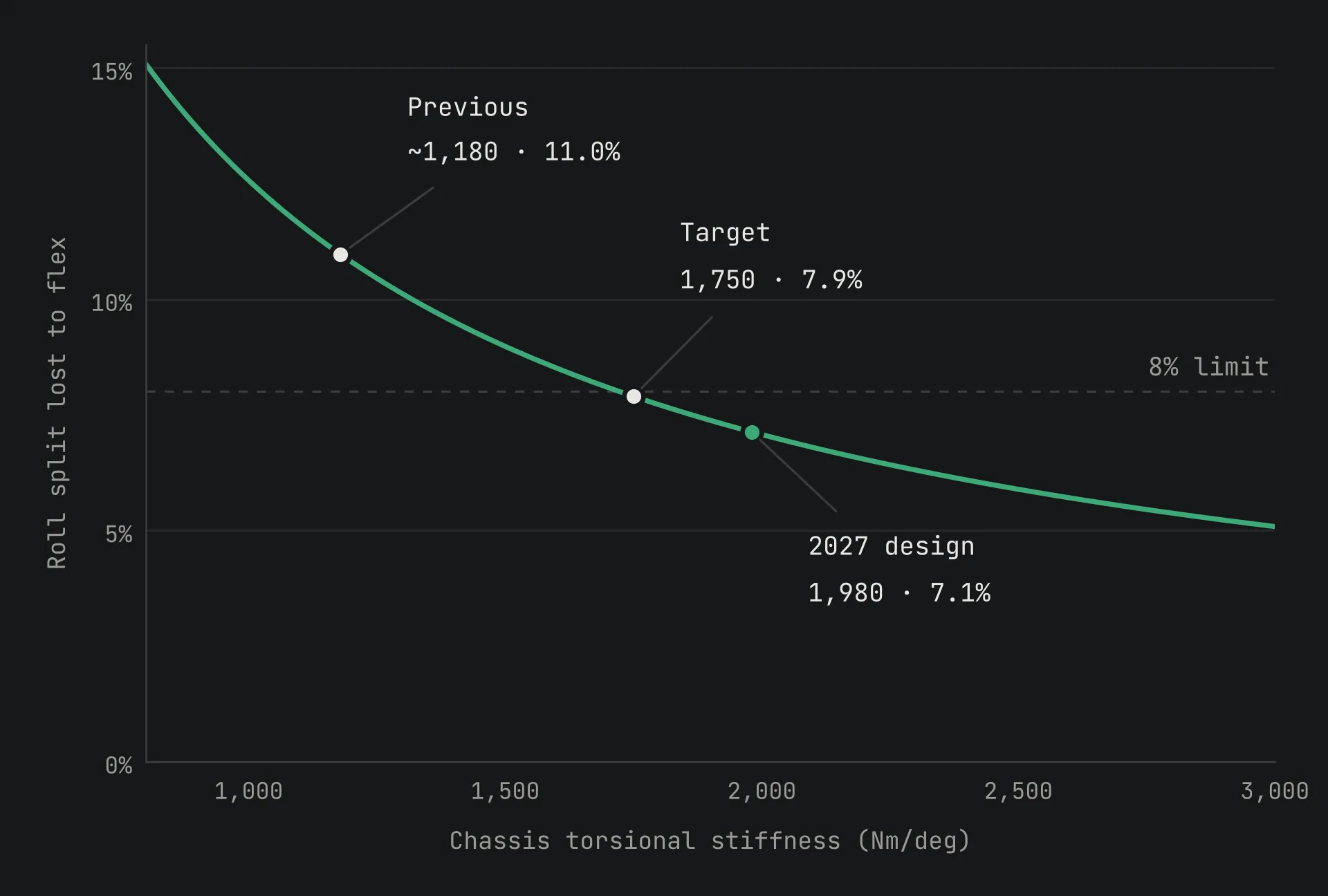
The chart plots the same model across a range of chassis stiffness. With this car’s suspension, the previous chassis would give away about 11% of the intended roll split, against about 7% for the 2027 design. The previous chassis’s stiffness is estimated by working back from the 68% gain.
Three designs into one
The chassis started as three parallel designs. We narrowed those to two, then combined the strongest ideas from each into one master design.
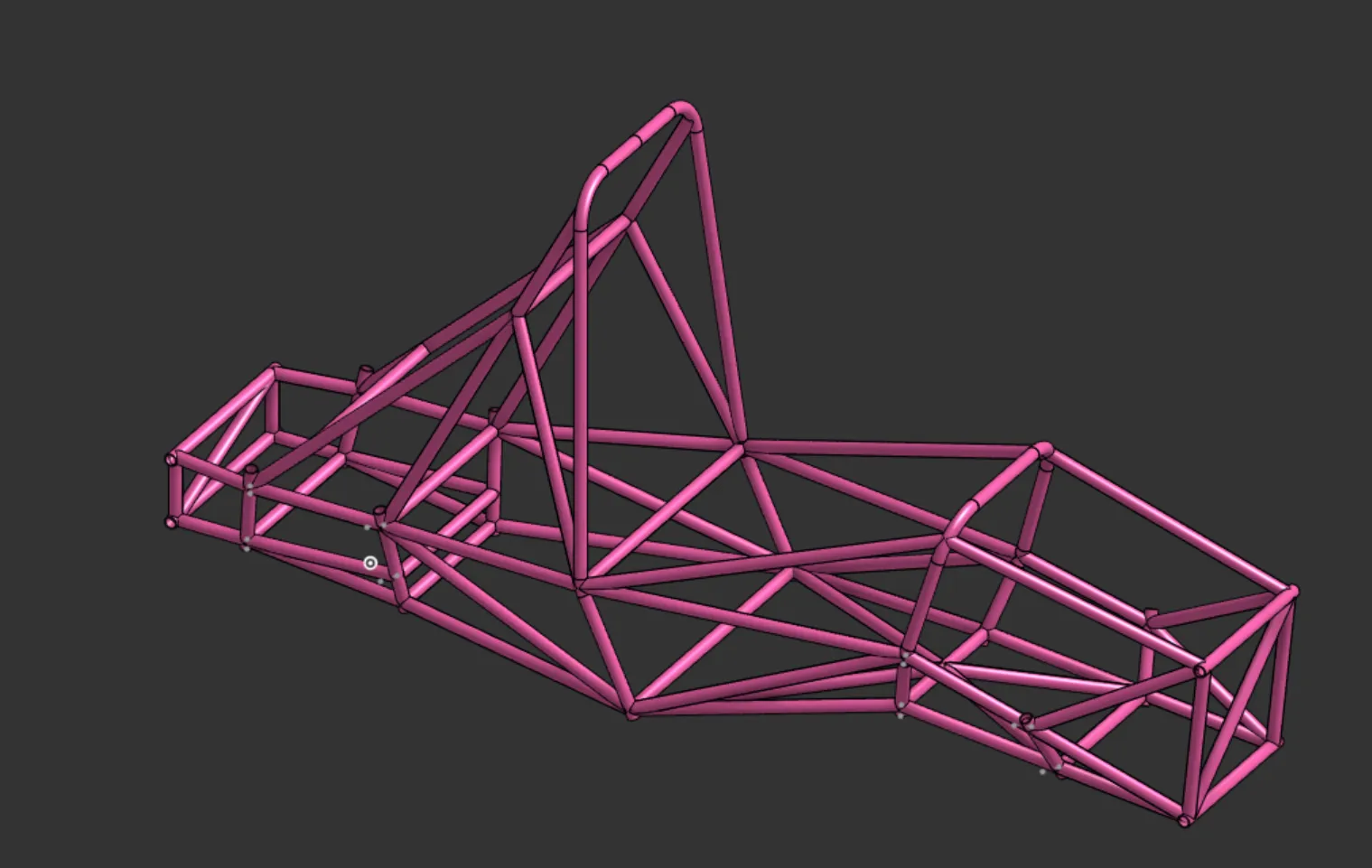
The stiffness came from three changes:
- Bigger tubes. A mix of 30 mm and 28 mm outside diameter tubes, up from 25 mm the year before.
- Better triangulation. I used the FEA displacement plots to find the points moving most, and in which direction, then routed new tubes to triangulate those points. Bays that had been carrying load in bending now carry it in tension and compression instead.
- Fewer tubes. Every tube that wasn’t earning its mass came out, which paid for the larger diameters.
Proving it
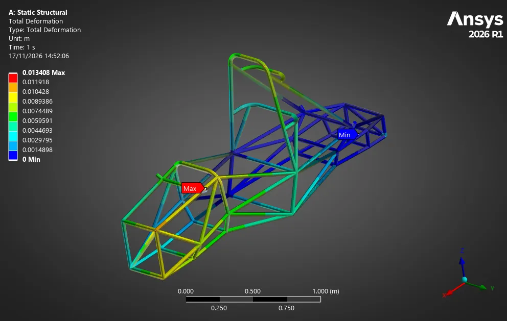
I validated the design in Ansys with a beam model of the frame and rigid suspension geometry. A torque is applied at the front axle with the rear held, then the reverse. The current design reaches 1,980 Nm/°, 13% above target and 68% stiffer than the previous chassis.
Mass
The bare frame comes in at 46 kg in 1020 steel, the same mass as last year’s. With every mount added, the current estimate is about 54 kg. That’s nearly 2 kg lighter than last year, even though it carries more mounts for the rocker suspension. The full-mount figure will firm up as the mounts are finalised.
Limits of the method, and how we’ll test it
The target is design guidance, not an absolute, and I wrote its limits into the report:
- It’s an idealised model. It treats the car as three torsional springs, with the chassis twisting uniformly between the axles. It ignores bending and local flex around the suspension pickups, assumes the same centre-of-gravity height at both axles, and doesn’t model anything dynamic.
- It isn’t validated yet. The method comes from a paper on an older Formula Student car, and we couldn’t compare it against that paper’s original curves.
- It hinges on one judgement: the acceptable loss. The source study allowed up to 20%. We chose 8%, because a smaller, heavier electric car is harder to balance. Small changes move the target a lot: with everything else the same, 7.5% calls for about 1,860 Nm/° and 10% for about 1,320 Nm/°.
- Load transfer is only a stand-in for handling balance. Tyres, roll centres, kinematics and the differential all play a part too.
Testing comes first. That means a static torsion test on the real chassis, with measurements at several points along its length and repeated loading and unloading to check for nonlinear behaviour. That’s paired with stiffness tests on the suspension corner assemblies and measurements of the real roll stiffness and centre-of-gravity height. Skidpad runs for understeer gradient and roll angle will then show whether the handling matches what the model predicts.
Where it is now
The chassis is in the final stages of analysis, ahead of release for manufacture.
Gallery · 1 images
The same torsion case with the undeformed frame overlaid, showing how the front of the chassis winds up relative to the rear.